Terms and Definitions
The horizontal plane upon which the bicycle is assumed to navigate.
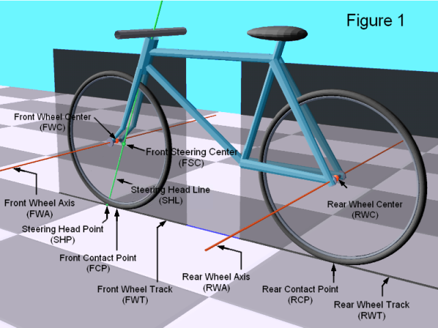
The line in space about which the front wheel rotates.
The line in space about which the rear wheel rotates.
The center point of the front wheel axis.
The center point of the rear wheel axis.
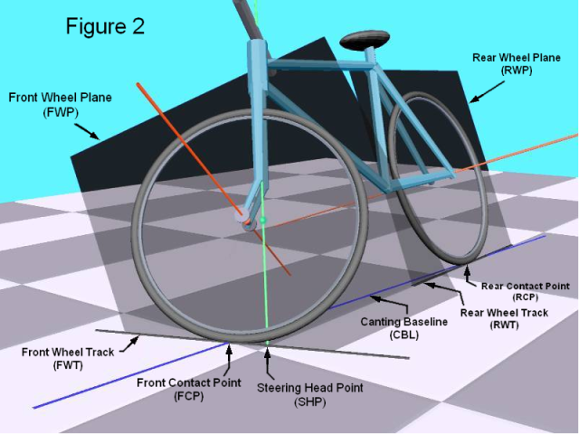
The plane in space defined by the orientation of the front wheel. This plane
is perpendicular to the FWA and passes through the FWC.
The plane in space defined by the orientation of the rear wheel. This plane
is perpendicular to the RWA and passes through the RWC.
The angle between the the FWP and the RWP (i.e., as viewed down a "steering column").
Note that this is generally NOT the degree of actual vehicle turning effected.
RWD = dist(FWC,RWC) when STEER = 0.
The horizontal component of RWD. RWB = RWD iff R1 = R2.
In general, one has RWB = sqrt( RWD^2 + (R1-R2)^2 ).
Note that during a turn, the effective wheelbase (EWB) will differ from the
reference wheelbase due to the steering and the cant of the bicycle in a turn.
The line in space formed by the intersection of FWP and RWP when STEER != 0.
This is the axis ordinarily associated with the steering column.
Also called simply the "steering head", this is the intersection of the SHL
with the GP (ground plane). Often given as a distance from the front wheel
contact point (FCP), it is said to be positive steering head (or positive
"castor") when located ahead of the FCP.
If the front wheel radius R1, the rake-angle SHA, and the front steering radius
FSR (aka, "offset") are known, one can calculate the steering head by
SHP = (R1*sin(SHA) - FSR)/cos(SHA)
Also referred to as the "rake" of the steering, this is the angle of the SHL
measured from vertical, when the RWP is held vertical. For the sake of
convention, we will assign a positive SHA for "normal" slanting rake.
The perpendicular distance between the SHL and the FWC.
Assuming that the front wheel radii R1, the steering head angle SHA, and the
steering head point SHP (as measured forward of the FRONT wheel contact point)
are known, the formula for calculating the front steering radius is given by
FSR = R1*sin(SHA) - SHP*cos(SHA)
The perpendicular distance between the SHL and the RWC.
Assuming that the rear wheel radii R2, the steering head angle SHA, and the
steering head point SHP (as measured forward of the REAR wheel contact point)
are known, the formula for calculating the rear steering radius is given by
RSR = SHP*cos(SHA) - R2*sin(SHA)
The contact point of the front wheel with the GP.
The contact point of the rear wheel with the GP.
The line in the GP formed by the SHP and FCP, or more generally, by the
intersection of the Front Wheel Plane (FWP) and the Ground Plane (GP).
This line gives the "heading" of the front wheel during a turn.
The line in the GP formed by the SHP and RCP, or more generally, by the
intersection of the Rear Wheel Plane (RWP) and the Ground Plane (GP).
This line gives the "heading" of the rear wheel during a turn.
The (ordinarily) acute angle formed between FWT and RWT.
If the rear wheel is held vertical at a heading of 0, the TURN is equal to the
relative Front Wheel Track (FWT) and is called the FWTURN, given by
FWTURN = atan( tan(STEER)*cos(SHA) )
The vertical line formed by the intersection of two vertical planes, the first plane
being perpendicular to the FWT and containing the FCP, the second being perpendicular
to the RWT and containing the RCP.
The bicycle's various "turning radii" are essentially distances measured from the TCL.
There are several radii that are of interest in describing the "size" of a turn.
If the issue is avoiding ground objects on the outside or inside of a turn, one is
interested in the Front Wheel Turning Radius (FWTR) or the Rear Wheel Turning Radius
(RWTR). These are the distances from the TCL to the FCP and RCP, respectively.
As the FWTR and RWTR are typically unequal, we can define the Greater and Lesser
Contact Turning Radii (GCTR and LCTR) to be the greater and lesser of FWTR and RWTR.
During a constant turn, the bicycle's wheels essentially trace two circles of size
FWTR and RWTR about the TCL.
As far as the dynamics of a turn are concerned, the Effective Turning Radius (ETR)
must be considered. This is the distance from the TCL to the bicycle's (and rider's)
center of gravity. Since a bicycle must be canted inward to a turn to maintain
balance, the ETR is always less than the GCTR, and is typically less than the LCTR.
The Canting Baseline is the line containing both the FCP and RCP. When canting the
bicycle into a turn, the bicycle is essentially rotating with respect to the GP about
the canting baseline. The "centrifugal force" created in a turn, on the bicycle's
center of gravity, must be sufficient to hold the bike at a constant angle to the
ground, in terms of rotation about the canting baseline.
Derivations
(forthcoming - please be patient)