Bicycle Geometry and the Z-Bike -

Toward the Design of an Optimal Recumbent


Preface

Lest I be misunderstood in discussing an "optimal" recumbent bicycle, I should clarify that I intend to mean a recumbent "for the masses", intended primarily for leisurely street and (somewhat) sporty touring considerations. I am not addressing the ultimate land speed record recumbent, not the ultimate recumbent mountain bike.

1.0 - Bicycle Geometry and Stability

The standard "upright" bicycle has reached a degree of near perfection. A well-made touring bicycle is an object of grace, performing the tasks demanded of it almost effortlessly. The fact that you can pilot a good bicycle hands free (not recommended) and even control gentle steering through minor shifts of weight and acceleration are a testament to the fine degree of balance the modern bicycle has achieved.

The goal of this exposition is to achieve this same degree of natural riding experience in a recumbent.

To understand the difficulties associated with this goal, we need to understand what makes a standard bicycle behave the way that it does. Three of the major qualities of bicycle geometry that make a bicycle ride naturally are

We take each of these in turn, and illustrate how they come together to produce a well-balanced machine.


1.1 - Steering Castor

Take any good upright bicycle, hold it in the straight and vertical position, turn the front wheel slightly, and then push the bicycle forward from the seat. Notice that the front wheel immediately tends to straighten toward the direction of motion. This effect is due to what is called positive steering castor, or positive steering trail, and is evidenced primarily during acceleration. Figure 1 below illustrates steering castor.

Negative Castor

The measure of steering castor, or trail, is given by the displacement of the steering head point (the extension of the steering tube axis to the ground) with respect to the wheel contact point with the ground. (A more accurate measure, from the standpoint of physics, would be the horizontal component of the displacement from the wheel contact point to the point on the steering head axis that is orthogonal to the axis, called the steering trail normal. However, either they are both positive, or both negative.) Figure 1a illustrates the effect of negative trail - as the bicycle accelerates forward, a small degree of steering will tend to become more severe, and the rider would need to exert additional effort against the direction of steer to keep the wheel tracking along the intended heading.

Figures 1b and 1c both illustrate positive trail, whereby acceleration tends the straighten the wheel to align with the direction of motion. This effect exists because a non-spinning wheel does not want to begin spinning on its own - one must overcome the wheel's rotational inertia to give it rotational (angular) momentum. The resistance to the gain in angular momentum is experienced by the wheel as if the ground is trying to drag the wheel toward the rear. The ground is essentially "grabbing" the wheel at its ground contact point and pulling it backwards. This will tend to straighten the wheel if the ground contact point is already behind the steering head point, but will move it further from straight otherwise.

Positive Castor

Positive Castor

Note that once a bicycle is moving forward in a straight heading at a constant speed, there is virtually no such "acceleration drag" affecting the front wheel (unless you have very bad wheel bearings). Hence, steering trail has only little to do with a bicycle's stability while coasting.

1.2 - Steering Lift

Refer again to figures 1b and 1c above. Both of these illustrate (good) positive steering trail, but they have poor steering lift (actually, 1c has negative steering lift, while 1b will exhibit negative steering lift as the bike is canted into a turn.) Steering lift refers to the degree to which the bicycle frame (or its center of gravity) either rises or falls as the wheel is turned. Take a good upright bicycle, hold it in the straight and vertical position from the frame near the steering tube, and then turn the wheel 45 degrees. You should notice that the frame has risen slightly, and that by pushing downward on the frame you will tend to cause the wheel to straighten and diminish the steering. This effect is due to a combination of two factors - the steering head angle (often called the rake angle) and the steering "offset", being the orthogonal distance from the steering axis line to the wheel center. I will refer to this distance as the "steering radius".

With small but positive steering lift, a rider should feel a slight pressure resisting the direction of steer. With negative steering lift, as the rider begins a turn, their own weight will tend to cause the wheel to "steer ahead" of their effort, or over-steer, and they must exert force against the direction of their intended steer in order to keep the steer from becoming greater than their intent. Figure 2a illustrates (severe) negative steering lift. If you attempted to ride such a bike "hands-free", and the wheel begins to turn, it will suddenly turn violently, despite the fact that this configuration has "great" steering trail.

Negative Steering Lift

Whenever there is no steering offset (steering radius = 0), and any amount of rake (rake angle) to provide for positive steering trail, there will be negative steering lift. This is because, with any rake angle, the wheel is only vertical when pointed straight ahead, and must depart from vertical as steering is applied. This causes the wheel center to drop closer to the ground. A steering offset which places the center of the front wheel above the line of the steering head axis can serve to counter negative steering lift caused by the canting of the wheel (figure 2b). As the wheel is steered, the front wheel center "orbits" backward and downward around the steering axis. The center of this orbit (depicted in green) is a point on the steering axis I will call the "steering center". With respect to the wheel center, the steering center must rise, and with it the frame of the bicycle, as steering is effected. In essence, the "offset" represented by the steering radius allows the wheel center to drop as the wheel cants over during a steer, while the steering center point can remain at a near-constant elevation.

Offset-Compensated Steering Lift

The precise amount of steering offset (steering radius) that will cancel negative steering lift depends upon the rake angle and the wheel radius. In general, the greater the rake angle (the more it departs from vertical) the more offset is needed to avoid a large negative steering lift. A "good bicycle" will have nearly flat steering lift, and tend to grow slowly as steering increases. With too much steering lift, the rider must exert excessive force in order to steer at all, as they are lifting themselves against gravity.

Finally, it must be mentioned that when a bicycle has any amount of steering offset, it is no longer exactly true to say that the bike has (say) front-wheel steering, or rear-wheel steering. In truth, both wheels are contributing to the steering. Just as we can define the Front Steering Radius (FSR) to be the perpendicular distance from the steering axis to the center of the front wheel, we can define the Rear Steering Radius (RSR) to be the perpendicular distance from the steering axis to the center of the rear wheel, as shown in figure 2c. Since (with a standard bicycle) the RSR is so large in comparison to the FSR, steering the front wheel 45 degrees to the right will only cause the rear wheel to "steer" 3 or 4 degrees to the left. (As we will see later on, it makes more sense to define front wheel steering as any configuration where the rider's seat remains stationary with respect to the frame of the rear wheel.)

Steering Radii

1.3 - Counter-Canting Steer

To get a sense of counter-canting steer, imagine you are riding at a good speed on a curved road in a constant and gentle right-hand turn. Naturally, you and the bicycle are slightly canted (leaning) to the right, toward the direction of the center of your turning circle, to maintain constant balance. Up ahead, you can see that the road will soon straighten, and you must prepare to eliminate this lean and bring the bicycle upright. How do you "un-cant" yourself?

There are two ways to accomplish this. One way is to accelerate, because as you travel along any circle, increasing your tangential velocity will increase the effective outward centrifugal force. Another way is to momentarily increase the degree of rightward steering, as this will cause the bicycle to begin tracking a smaller turning circle, and (again) increase the effective outward centrifugal force.

But this is not the whole story. Consider a bicycle with "naive" rear-wheel steering (where the RSR is smaller than the FSR). To maintain the same gentle right-hand turn described in the previous paragraph, the rear wheel is steered to the left. If the steering is momentarily increased (the rear wheel is turned further to the left), the bicycle is indeed "tracking a smaller turning circle", and must eventually produce a greater outward force. But the immediate effect is that the rear wheel is initially tracking this new circle to the left, causing the cant of the bicycle to increase rather than decrease, until the rear of the bike swings around to the far side of this new turning circle. This is a very unsettling and counter-intuitive effect.

Constant Turn

Figure 3 illustrates what is really happening with standard front wheel steer (where FSR < RSR) and "naive" rear wheel steer (where RSR < FSR). Figure 3a represents a bicycle in a constant right-hand turn. I have purposely drawn it so that both the front and rear wheels are tracking the same turning circle, leaving it ambiguous as to whether this is front wheel or rear wheel steering. Notice that you find the center of the turning circle at the intersection of the two vertical planes (green lines) containing the ground contact points of the front and rear wheels, and each perpendicular to the tracking direction of the respective wheels. The red line, denoted the "turning arm", connects the center of the turning circle to the bicycle's center of gravity, and the blue arrow indicates the direction of the bicycle's current heading (direction of momentum). (If the bike were to hit "frictionless ice" at this moment, the bike would slide along the blue line.) Note that the blue momentum line is exactly tangential to the current turning circle, and perpendicular to the turning "arm".

Front Wheel Steering

Figure 3b shows what happens with front wheel steering, if the rider suddenly increases the amount of rightward steer (and the tires do not slide.) Notice that not only has the new turning circle gotten smaller, its center has moved *behind* the red line of the previous turning circle. This means that the bicycle's current momentum line is no longer tangential to the new turning circle, but is actually heading *away* from the circle, and away from the tangent heading of the new turning arm. This effect is what is immediately responsible for lifting the bike up from its current canting angle, and is what I will define as Counter-Canting Steer. Importantly, note that suddenly turning the wheel provides the bike a new "tangent heading", but does not immediately alter the momentum heading.

Rear Wheel Steering

Figure 3c shows what happens with (naive) rear wheel steering, if the rider suddenly increases the amount of leftward steer to the rear wheel to force a "sharper" right turn. Again, the new turning circle has gotten smaller, but now its center has moved *ahead* of the red line of the previous turning circle. This means that the bicycle's current momentum line is carrying the bicycle *into* the new circle (compared to the new tangent heading) rather than away from it. This is what will cause the bike's canting angle initially to *increase*.

It should be clear from these diagrams that one must have FSR < RSR (modulo rake angle) in order to have counter-canting steer. Specifically, with the bike canted into a turn, extend the steering head axis to the ground and call this the "steering head point". This point also lies on the intersections of the lines representing the directions of the front and rear wheel tracks. The line segment connecting the front wheel contact point to the steering head point, and the segment connecting the rear wheel contact point to the steering head point, are essentially the "shadows" cast by the FSR and the RSR upon the ground, if light shines down in parallel to the steering head axis. It is actually the FSR-shadow that must be shorter than the RSR-shadow that is required to have counter-canting steer.

Wheel Diameter

Another property that upright bicycles enjoy is the ability to easily accommodate large wheel diameters on a relatively short wheelbase. Having large wheel diameters provides two benefits. First, it allows the bicycle to moderate the jarring effect of small bumps in the roadway, thus lessening the need for suspension. Figure 4 depicts a 15" and 30" wheel encountering a 2" curb. Note that upon "impact", the path of the smaller wheel center must make a larger instantaneous change of trajectory (red arrow) in order to ride up and over the curb. A second benefit is added gyroscopic stability at high speed. (If you can find a long, steep, well-paved and isolated roadway, take a good 26-inch bike to top speed on a downhill run. As you approach 50-60 MPH, try to "recklessly" swerve the bike left and right - it is almost impossible. As far as steering and canting goes, the bike acts like it is moving through molasses.)

Effect of Wheel Diameters

In summary (so far), one can appreciate why the standard upright bicycle, with its moderate rake angle (as measured from vertical), its moderate steering offset (FSR) and moderate trail come together to forge the finely balanced machine that so many people enjoy. Any bicycle, be it front or rear wheel steer, front or rear wheel drive, upright or recumbent, cannot stray far from a careful relationship among these settings and produce a "naturally" rideable machine.

With these considerations (and some others) in mind, let us set forth to design the "ultimate" recumbent bicycle.


2 - Recumbent Bicycles

2.0 - Recumbent Position Pros and Cons

To begin, I should reiterate that my goal here is not the ultimate recumbent for professional racing, but rather to develop a recumbent bike for the casual touring cyclist, while retaining much of the "sporty" handling of a fine upright bicycle.

Generic Rider Positions

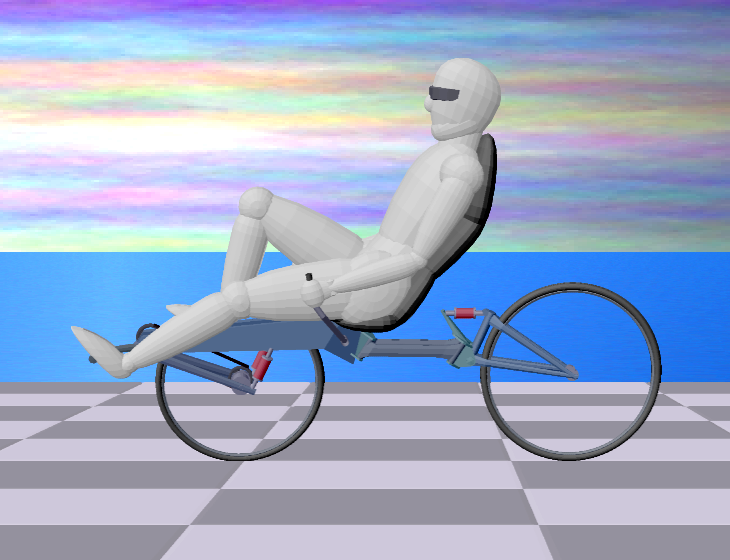
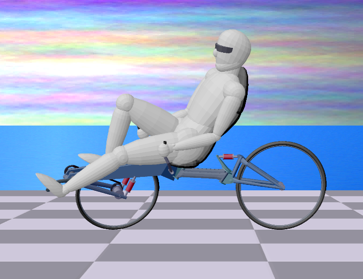
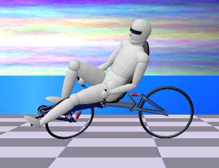
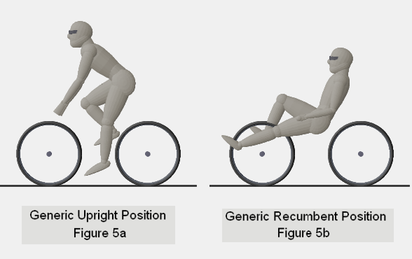
Refer to figure 5 to compare the general orientation of the rider, in the upright versus recumbent positions. Each position has positive and negative attributes, independent of the particular bike being ridden. Let us consider some of these:

Here, the recumbent generally provides better aerodynamics, as there is less frontal area exposed. To approach a similar degree of aerodynamic in an upright, the rider must double over into the "racing position", which requires the rider to carry their upper weight on doubled-up arms, and to crane their neck backwards in order to see forward.

Almost anyone can balance a 6-foot broom-handle upright on the tip of a finger. Try to do the same thing with a 6-inch pencil, and you can appreciate why "tallness is good" when it comes to maintaining balance. The upright rider can adjust their weight and position easily to control the bicycle in motion. This is more difficult for the recumbent rider, especially with recumbents that seem to strive for the "limits of lowness" in rider position. For this reason, having good "inherent balance" in a bicycle's geometry could be said to be more important for a recumbent than for an upright bicycle.

In the upright position, the legs receive superior blood-flow, and one can argue that humans have evolved to conduct most all of their heavy exertion in the upright position (with certain horizontal exceptions ... ). Some recumbent riders complain of numbness in their feet or toes after a long ride. For this reason, a "good" recumbent would sacrifice some of that horizontal streamlining for a slightly rider-canted position (pedal crank lower than the rider's seat). Of course, the head and torso receive better blood-flow in a recumbent position.

When encountering a patch of rocky roadway, the (alert) upright rider can lift themselves off the seat, and use their legs as shock absorbers, lessening impact upon the body (and lessening the chance of wheel damage). In contrast, the recumbent bicycle must carry the rider's full weight at all times. This makes full-suspension more a necessity than a luxury for the recumbent, adding weight to the frame.

The well-designed recumbent is the clear winner here, as one of the main motivations for recumbent bicycles is to provide the casual rider with a more comfortable riding experience. Even the best upright touring bike requires that the rider's upper body be canted a bit forward, and support a bit of this upper-body weight on the arms. This can become tiring on long outings, and the forward cant of the upper body means that the neck must continuously lift the head up and backwards to look forward at a natural angle. The recumbent addresses all of these issues well, but at the price of a (typically) heavier bicycle, requiring full suspension and a larger seat to support the upper back.

Arguably, a recumbent designed for speed can exceed the speeds achievable from an upright bicycle. With a recumbent, the full force of a rider's legs can be applied between the pedals and the back of the rider's seat, and most people can "leg press" far more than their own weight. It is said that an upright rider can only exert pedal force equal to their own weight. While this is not entirely true (the rider can "lift upward" on the handle bars while pressing down with the legs) this can quickly become an exhausting proposition, and can interfere with steering control. However, the salient question here is whether one can obtain speed from a "casual" touring recumbent, comparable to that of a similar upright. I think the answer is a qualified "yes", depending upon the specifics of the recumbent design.

There is little that can be done for the upright bicycle that would serve to mitigate its shortcomings. It can be argued that the recumbent position has as many, or more shortcomings, overall. However, recumbent designs allow for greater 
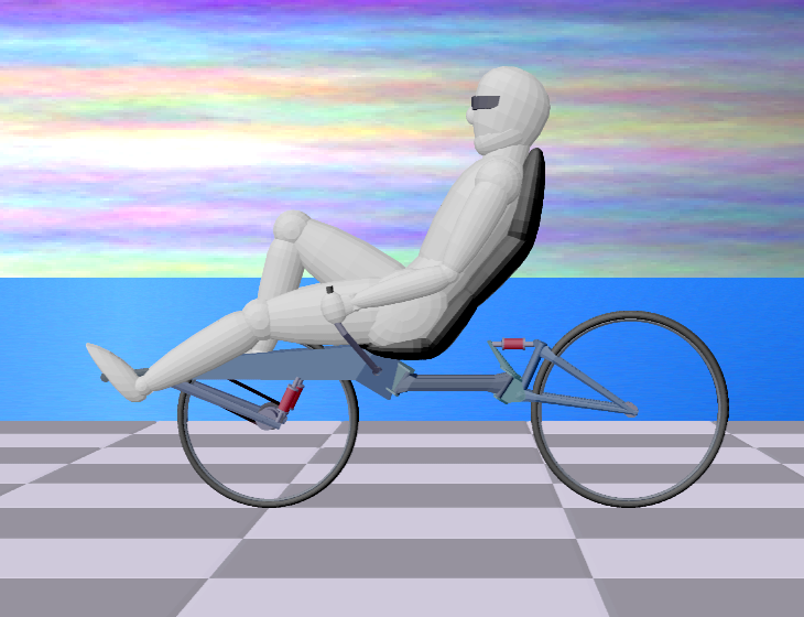
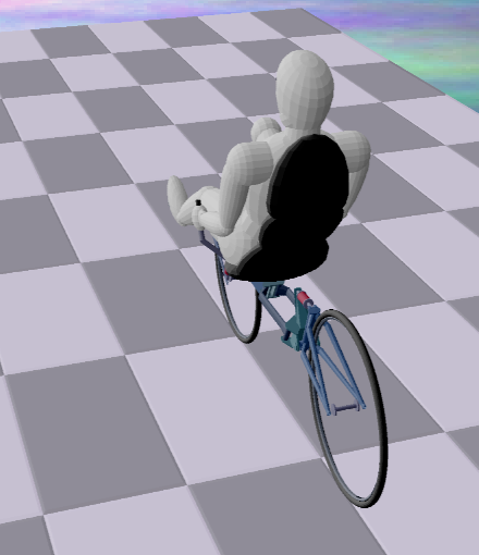
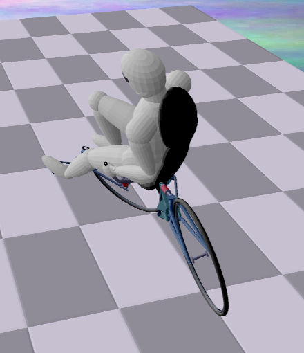
flexibility that can serve to mitigate most of these issues. Consider figure 5b, where I have intentionally drawn an ambiguous (almost impossible) recumbent position - the pedal crank would have to pass through the front wheel. Having to "design around" this particular difficulty is responsible for much of the variety one sees in recumbent designs. As we shall see, these design "solutions" often lead to their own unique drawbacks, and further unique solutions.

Terminology

Recumbent bicycle designs can be divided several ways, the most common being

and to a less common extent

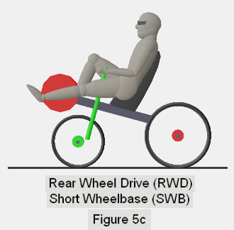
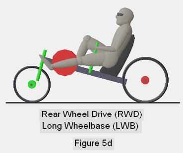
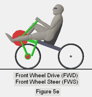
Below, I depict (figuratively) each of these designs (or their most common implementations) and discuss what I feel are the gains and losses associated with each. I begin with the Rear Wheel Drive designs, then move on to Front Wheel Drive and then "Rear Wheel Steer", as this order provides a nice sequence of problem-solution-problem motivated alterations.

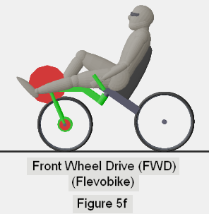
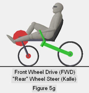
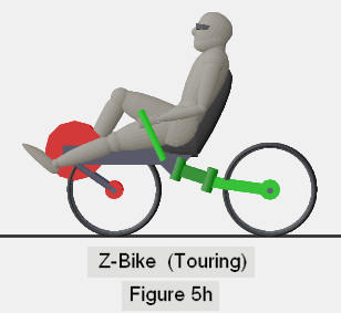
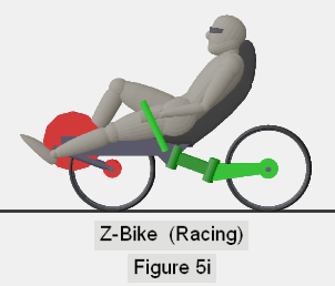
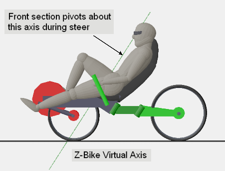
With each figure, I use red disks to indicate the "powered" wheel, and the travel of the feet around the pedal crank. I use a green disk to identify the wheel that steers, and green for any major frame components that move together with the wheel during a steer. The remainder of the frame is depicted in dark gray.

2.1 - RWD - SWB

One of the first "equations" we can write for recumbents is that RWD = VLC (very long chain). I consider this to be a largely negative feature (the entire chain-path must be protected from interference with body and clothing, and it requires many intermediate and noisy chain-guiding rollers). It is largely unavoidable with Rear-Wheel-Drive recumbents, both for short and long wheelbase designs.

Rear-Wheel-Drive with Short-Wheelbase

Refer to figure 5c for the most general Rear Wheel Drive, Short Wheelbase design. Notice that the short wheelbase is accomplished by placing the pedal crank above and forward of the front wheel. This allows the rider to address the steering directly at the steering tube, as with an upright bicycle. However, the frame must pass well over the front wheel to place the pedal crank in this forward position, and the entire pedal foot-travel (large red disk) must also be kept above and away from the front wheel itself, to avoid interference of feet with the wheel as it swings left and right during steer. Thus, one tends to see a small front wheel used in this design (smaller still, if front wheel suspension travel is to be accommodated.) Raising the feet this high demands that the rest of the rider be lifted up as well, so that the feet can at least be kept to a height no greater than that of the seat. Hence, this is generally not a "low profile" design. Also, as the rider's upper legs must straddle the steering tube, the handlebars must either rise uncomfortably high to allow for knee movement, or else "under seat steering" (USS) must be employed. I find both of these steering alternatives, and the generally small front wheel, to be "sub-optimal".

2.2 - RWD - LWB

Figure 5d depicts the Long Wheelbase alternative for Rear Wheel Drive. Here, the pedal crank is maintained at a lower altitude by placing the front wheel ahead of the pedals.

Rear-Wheel-Drive with Long-Wheelbase

The major downside to this design is generally the wheelbase itself - a long wheelbase demands a longer (and heavier) frame, heavier due both to the increased length and to the need to make it "beefier" to reduce flexing. Also, in order to make the steering tube axis (rake angle) approximate that of a good standard bicycle, a means of steering the front wheel "remotely", via chain or other linkage, is often employed. One positive note regarding LWB design is that it allows for a great flexibility in certain specifics. In principle, one could lower the rider as much as desired, recline the rider further, and even use larger wheel diameters with this design - but each of these things would require making an already long frame even longer. Lastly, a long (and low) frame risks the bike "bottoming out" when navigating uneven and rolling surfaces, and making sharp turns to navigate crowded spaces is obviously problematic. For these reasons, LWB designs are more fit for specialized racing considerations than for the casual cyclist, and I tend to reject LWB designs when considering the "ideal" sport/touring recumbent.

2.3 - FWD - SWB (FWS)

The solution to "Very Long Chain" is to power the front wheel, as this is the general location of one's feet in a recumbent position. Unfortunately (for most designs), the front wheel is also the wheel that is expected to effect steering. The "lateral inflexibility" of chain drive means that the pedal crank must be kept fixed in, and perpendicular to the plane of the wheel being driven. Hence, as one steers the front wheel left and right, the entire pedal system must swing left and right along with the wheel. This places interesting constraints on front wheel drive bicycle designs.

Front-Wheel-Drive with Front-Wheel-Steer

With the rider seated on the "rear" of the frame, and behind the axis of the steering tube (figure 5e), the rider must "pivot" in their seat during a steer. Seats that pivot are made to accommodate this design. However, as (say) rightward steering is increased, the distance from the seat to the right-half of the pedal crank becomes shorter than the distance to the left side of the crank. Ones legs must adjust, I would say "unnaturally", to accommodate such a steering arrangement. This situation can be (almost) eliminated by placing the steering tube further back, at a rake-angle closer to 45 degrees. This allows the rider's upper body to be "seated" more directly above the steering pivot point and in line with the steering axis, reducing the "length-changing" effect (see figure 5f). This design is employed in the "Flevobike", and probably comes closest to optimizing the "rear-seated" front wheel drive design.

Front-Wheel-Drive with Front-Wheel-Steer (Flevo)

These FWD designs still have some drawbacks. First among these is that, as the feet alternate pedal force left and right during acceleration, the front frame of the bike wants to "steer" (right and left, respectively) at the same time, a condition I refer to as "unwanted pedal steer". The rider must try to control this effect through a countermanding force applied to the steering. While pedal steer is minimized with the Flevobike design, I do not believe it can be eliminated entirely, due to the fact that the rider is seated on the rear of the frame. As well, the need for the rider to be behind, and above the steering tube location means using a smaller front wheel, or else raising the pedal crank (and thus the rider) to a higher position.

2.4 - FWD - SWB ("RWS")

But who says you must "ride in the back"? Why not take the front seat?

A radical alternative for Front Wheel Drive design is the Kalle FWD, "Rear Wheel Steer" design. I quote the words "Rear Wheel Steer" because (as one person wrote) the Kalle can be thought of as front wheel steer - with the rider positioned on the handle bars. Note that the position of the steering tube allows the bike to maintain a reasonable steering geometry. I will call this Rear Wheel Steer, precisely because the rider remains in fixed alignment to the front wheel (and pedal crank) during a steer, while it is the rear wheel that moves "out of alignment" with the rider during steer.

Front-Wheel-Drive with Rear-Wheel-Steer (Kalle)

Unlike the rear-seated FWD designs, the Kalle allows the rider to be "one" with the drive system (pedal crank and drive wheel) while steering. More so than the Flevobike, this design entirely eliminates both the "seat-to-pedals length-changing" effect during steer, and the unwanted pedal-steering effect, as the rider, the seat, front wheel and pedal crank are all a fixed part of the front "steering unit."

The Kalle design also tends to place the steering tube at an increased rake-angle, superficially similar to the Flevobike. However, while the Flevobike tends toward this arrangement to minimize leg-distortion and pedal steer, the Kalle does so for a very different reason. Recall section 1.2 above regarding steering lift. We discussed how steering lift is largely a function of rake-angle and wheel offset, and why both large negative and large positive steering lift should be avoided. This "proclamation" holds true for most bikes, because the rider is seated on the rear of the frame, and only rises (or falls) to a fractional degree, determined geometrically by the orbit of the steering center. In contrast, the Kalle rider moves with the front wheel during a steer. A configuration of rake and offset that would produce almost flat "geometric" steering lift (such as with a standard upright bicycle) could result in enormous "effective" steering lift if the rider sat atop the handle bars and well behind the steering tube. If one imagines a vertical steering tube, the rider could sit anywhere "off axis" and not rise as they rotate around the axis. But if the axis is tilted back, and the rider is back behind (and below) this axis, rotation about the axis must lift the rider upward. This would result in considerable resistance to any increase of steering angle. Two ways to mitigate this effect are either to decrease the wheel offset for any given rake angle (resulting in negative geometric steering lift to compensate for the rider's lift with respect to the frame) or to move the rider's center of gravity closer to the steering axis. Some combination of both of these should result in the "sweet spot" that provides a nearly flat, or slightly positive steering lift.

However, when it comes to rider seating height and front wheel diameter, these "Kalle" designs suffer from the same issues that the rear-seated FWD designs must negotiate - the steering tube must remain above and behind the front wheel center in order to maintain reasonable steering axis and rake, and then the rider must remain atop this point in order that the steering components can move freely left and right beneath the rider. As well, the front frame must pass well over the front wheel to mount the pedal crank in the desired location (and more so if front wheel suspension travel is to be accommodated). These considerations generally force FWD designs, whether "Flevo" or "Kalle", to settle for a smaller front wheel, and even this only partially addresses the "high rider" issue.

Can we "solve" both of these remaining problems? At once?

2.5 - The Z-Bike

Here, I propose two "radical" modifications to the Kalle FWD-RWS design, in a design I have designated the "Z-Bike".

The first of these modifications is not terribly radical, and certainly has its own weight-related downside. Construct the front frame to straddle both sides of the front wheel while remaining open at the top, allowing the wheel to move up and past the top of the frame for suspension travel, and allowing the crank to maintain a lower position forward of the front wheel.

Front-Wheel-Drive with Rear-Wheel-Steer (Z-Bike Touring)

Front-Wheel-Drive with Rear-Wheel-Steer (Z-Bike Racing)

This "split frame" (in itself) would not allow for a much larger front wheel, nor a much lower rider position, as the rider's legs must still reach across the wheel diameter and allow room for the steering tube. Larger front wheel and lower crank position only becomes possible when the rider can get closer and "more intimate" with the front wheel, a generally impossible situation, because there is then no room to place the steering tube and allow the rear steering assembly to move freely beneath the rider.

With the Z-Bike, the steering tube is replaced by a pair of swiveling arms in a trapezoidal arrangement (see figure 6). This steering mechanism can be placed well behind the location of the would-be steering tube, and at various elevations, yet it will cause the bike to "fold" at a point that approximates the standard steering tube position - what I will call the "phantom steering tube" or "phantom steering axis". One can adjust the "phantom" rake angle directly by the angle in which the steering assembly mounts to the front frame, and can adjust the "phantom" front steering offset either by the selection of mount point, or by the length of the swivel arms employed, or even by the ratio between the separation of the front steering pivots and the rear steering pivots.

Z-Bike Trapezoidal Steering

Figure 6a illustrates the steering arrangement of a standard upright bicycle, from a "top view" (actually, from a view that aligns with the steering tube, depicted as a red circle offset from the front wheel center). The "rear frame" is depicted in blue, and the horizontal gray line maintains the front and rear wheel ground contact points. With figure 6b, a 30-degree left steer is shown (with bike held vertical). Notice that the steering tube has shifted to the right, and that the rear wheel is actually "steering" about 4 degrees to the right. This has also resulted in moving the rear wheel forward, shortening the wheelbase by some fraction of an inch. (Of course, in a "real" 30 degree steer, the bike would be canted over to the left, and the wheel contact points would move further apart, actually increasing the effective wheelbase.)

Figure 6c illustrates the Z-Bike steering mechanism, before steering is applied. Note that the two steering arms (depicted in red) form a trapezoid, as the pivot points near the front wheel are closer together than those near the rear wheel. With figure 6d, a 30-degree left steer is shown. The large red circle on the front wheel indicates where a "standard" steering tube would appear, and is now the "phantom" steering tube. Note that at 30 degrees of steer, the rear wheel still steers about 4 degrees to the right, and remains pointing (approximately) to the phantom steering tube, as if the rear frame was rotating about that point. (Note also, the "double-bent" shape of the frame during a steer is reminiscent of the letter "Z", hence the "Z-Bike" name.)

With any solution, new "problems" appear. There are indeed drawbacks to the Z-bike mechanism. Careful examination of figure 6 would show that, as steering is increased, the "phantom" steering tube actually drifts backward a bit (increasing the front steering offset), and the rear wheel has moved several inches closer to the front of the bike, diminishing the wheelbase and causing steering to increase the degree of turn effected. (Alternately, one could argue that less "steer" is needed to effect an equivalently sharp turn for the bicycle as a whole.) In any case, geometry will show that these effects can be reduced by lengthening the two steering arms and moving the mechanism back a bit further from the front wheel, at the expense of lengthening the overall wheelbase.

Another potential drawback to the trapezoid-arms steering system is that it is very difficult to obtain an effective steering angle of more than about 50 degrees. Of course, one rarely applies such a sharp steering angle except when practically at a standstill, or walking the bike, and by then the bike's overall wheelbase will have been reduced to such an extent that 50 degrees provides for a very small turning radius, such as one might obtain at 60-65 degrees of steer for a standard bike.

Of course, a more general drawback to the Z-bike design is simply its structural considerations. Although it affords a rather sleek, "compact" and unified framework, that framework is still rather substantial, weight-wise. With its additional complexity comes additional expense – the single thrust-bearing-housed steering tube of a standard bicycle becomes four such (albeit smaller) tube-assemblies with the Z-Bike, to accommodate the four pivot-points of the trapezoidal steering mechanism. In its favor, one could design an adjustable mount point (location and angle) for the front pivot assembly, along with "replacement" pivot arms of various lengths, that would easily allow one to create a very wide range of bicycle geometries.

On another positive note, notice that this design allows the pedal crank to be further ahead of the front wheel, and lower, than with any other FWD design. Since the chain travel from crank to wheel most be kept relatively constant, a suitable front suspension (that does not jar the rider's feet) demands that it pivot very close to the crank. Other FWD designs must place the crank so far above the front wheel, that such suspension travel moves the wheel more "backwards" than upwards, an issue that is addressed well in the Z-bike design.

There is one more issue that must be mentioned with all "Kalle" type bicycles. For all RWD bikes, the front wheel can be steered "very rapidly" to the left or right if desired, since it is only the front wheel, fork and handlebars that are at play. However, with the Kalle (and to a lesser extent, all FWD designs) far more mass exists to be rotated to effect a change of steer. Although we might call Kalle-type designs "rear wheel steer", we fully expect that as we pull upon the handlebars it will be the front section (and rider with it) that performs most of the "turning". There is a danger that, with too much front-loading of weight, together with the angular inertia presented by the rider, an attempt at a "sudden left-hand steer" might cause the rear section to slide to the left, rather than stay put and allow the front section to turn left. Mitigating this potential requires moving the rider back and increasing the "recumbency" (moving more weight toward the rear), while ensuring that the majority of the rider's mass remain as close as possible to the steering axis (real or phantom). This (once again) leads us toward a bit smaller front wheel.

Summary

Having confessed to its variable deficiencies, I feel that the Z-Bike "solves" the major issues I see with the standard Kalle design (and other recumbent designs in general).

In summary, the Z-Bike accommodates all of the following design goals:

Given the outlined Z-Bike design, there exists room for further innovations (a variety of specific mechanisms to apply steering force to the trapezoidal steering system can be developed, for example.) But whatever improvements exist to be made, I believe they will center around the Z-Bike configuration on a path to the ultimate sport-touring recumbent.

Additional (Computer-Generated) Images

Below I intend to provide additional images of possible Z-bike implementations. Enjoy!

zbike-rearview25-1-md

Here is a detail view of a potential steering mechanism, using a ball-and-socket linkage between the handlebar pivot arm and the trapezoidal steering arm.

zbike steering mechanism

zbike virtual steering axis

It may be counter-intuitive to view this image and SEE the virtual steering axis. One tends to imagine that the bike could fold (rotate) independently about either the front, or rear steering pivots. However, the trapezoid location of the 4 pivots actually constrains the steering arms so that they cannot pivot independently, and the bike is thus forced to behave as if a steering tube were present along the indicated green line.

Here are several images that show the Z-bike in various degrees of steering (and canting.) Each sequence of four images depicts 0, 10, 20 and 30 degrees of steer, in concert with 0, 10, 20 and 30 degrees of front wheel canting (leaning) into a turn.

NOTE: If you download these images and save them to a separate folder, you can view them with (say) Windows Picture and Fax Viewer (surely the Mac has something similar), and rapidly click the next-image button to get a sense of the bike as its steering is increased.

zbike 0 steer

zbike 10 steer

zbike 20 steer

zbike 30 steer

NOTE: If some images do not appear, you may need to click browser-refresh.

zbike 0 steer

zbike 10 steer

zbike 20 steer

zbike 30 steer


[ Home ]